Industridesign
Færdige projekter, der opfylder industrielle krav.
Disse løsninger omfatter tilpasninger, foreløbige designvarianter, lastberegninger, konstruktions- og geoteknisk design samt svar på særlige krav.
Færdige projekter, der opfylder industrielle krav.
Disse løsninger omfatter tilpasninger, foreløbige designvarianter, lastberegninger, konstruktions- og geoteknisk design samt svar på særlige krav.

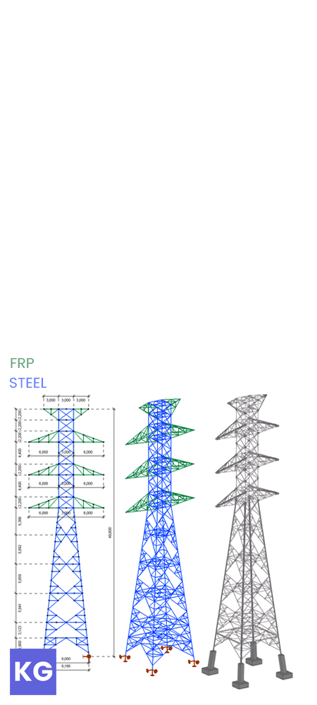
50 meter høj ståltårn med pultruderede FRP-tværarme, designet med henblik på vægtreduktion.
Denne hybride konstruktion var kernen i mit bachelorprojekt og modtog senere Diplomprisen fra den Ungarske Stålforening.

Konstruktionen bærer et dobbelt trefaset kredsløb med jordledere.
Lederne og jordlederne er monteret på henholdsvis de nederste seks og øverste to FRP-tværarme.
Stålkroppen består af:
Benstivere,
To typer hovedgitter,
To typer horisontalt afstivning,
Sekundær afstivning.

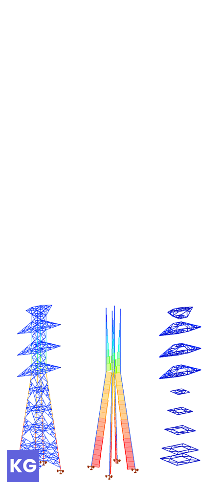
FE-model: 6DOF bjælkemodel med ledunderstøtninger.
Analyse: Elastisk, førsteordens
Standarder: EN 1993-3-1; EUR 27666 EN
Beregningerne bestod hovedsageligt af tværsnitsverifikationer i ULS, suppleret med i planen stabilitetskontroller af afstivningssystemerne. Begrænsning af trækspændinger i FRP-elementer viste sig nødvendig for at undgå krybesprække ved kvasi-varige belastninger.

Alle forbindelser blev beregnet manuelt.
Designet af disse samlinger blev udført i henhold til EN 1993-1-8 og EUR 27666 EN.
Brudformer for stålbolte inkluderer skær og tryk, samt nettotræk, stifttryk og udskæring for FRP-profiler.

Komplekse samlinger ved krydsningerne af tværarme.
Forbindelseskapaciteten i skrå samlinger viste sig at være den største udfordring ved brug af FRP, da dets ugunstige styrke måtte anvendes på grund af materialets ortotropi.

Generel arrangementstegning for den nederste del af stålkonstruktionen.
Oprettet i Tekla Structures.

Generel arrangementstegning for den øverste ledertværarm.
Oprettet i Tekla Structures.

36 meter spændvidde industrielt stålbygning med kompositdæk og trækstangsafstivning.
Dette omfattende projekt, udført som en del af mit industriprojektarbejde på BME, indeholder næsten 500 sider dokumentation og over 100 tekniske tegninger.

Rumlig og overfladedannelse var udgangspunktet for projektet.
Derfor skabte jeg den vertikale og horisontale opbygning af bygningen, tilpasset funktionerne. Jeg valgte også passende beklædningstyper til vægge, tag og gulv.
Dette blev udarbejdet i en skematisk BIM-model, detaljeret nok til at jeg kunne fortsætte designprocessen.

De mellemliggende rammers primære bærende elementer er svejsede stål-SHS gitterdragere samlet i tre dele.
Gavlene er portalrammer med koniske bjælker og bærende søjler for facadebeklædning.
Horisontale laster optages af trækstangsafstivning, som udviser materialenonlinearitet i modellen.
Et afskærmet område med kompositdæk er også implementeret for at understøtte forskellige funktioner i bygningen.

FE-model: 7DOF bjælkemodel med indspændte understøtninger.
Analyse: Ikke-lineær, andenordens.
Standarder: EN 1993-1-1, 1-3, 1-4, 1-5, 1-11; EN 1994-1-1; EN 1998-1.
Beregningerne omfatter dimensionering af sekundære elementer (sandwichelementer og Z-spær), kompositdæk, alle stål tværsnit, afstivning kun i træk og fundamenter.
Lokale og globale stabilitetskontroller samt seismiske responser blev også verificeret, sammen med nedbøjninger og sideforskydninger.

Samlinger, beslag, knudeforbindelser med gussetplader og svejsede forbindelser for primære gitterdragere blev alle verificeret ved manuelle beregninger i overensstemmelse med EN 1993-1-8.
Andre samlinger, såsom fodpladesamlinger for søjler og endeplader for gavlene, er blevet dimensioneret ved hjælp af Consteel Joint.

Plantegning af den færdige bygning med en konstruktionsvisning i venstre halvdel og en arkitektonisk visning i højre.
Oprettet i AutoCAD.
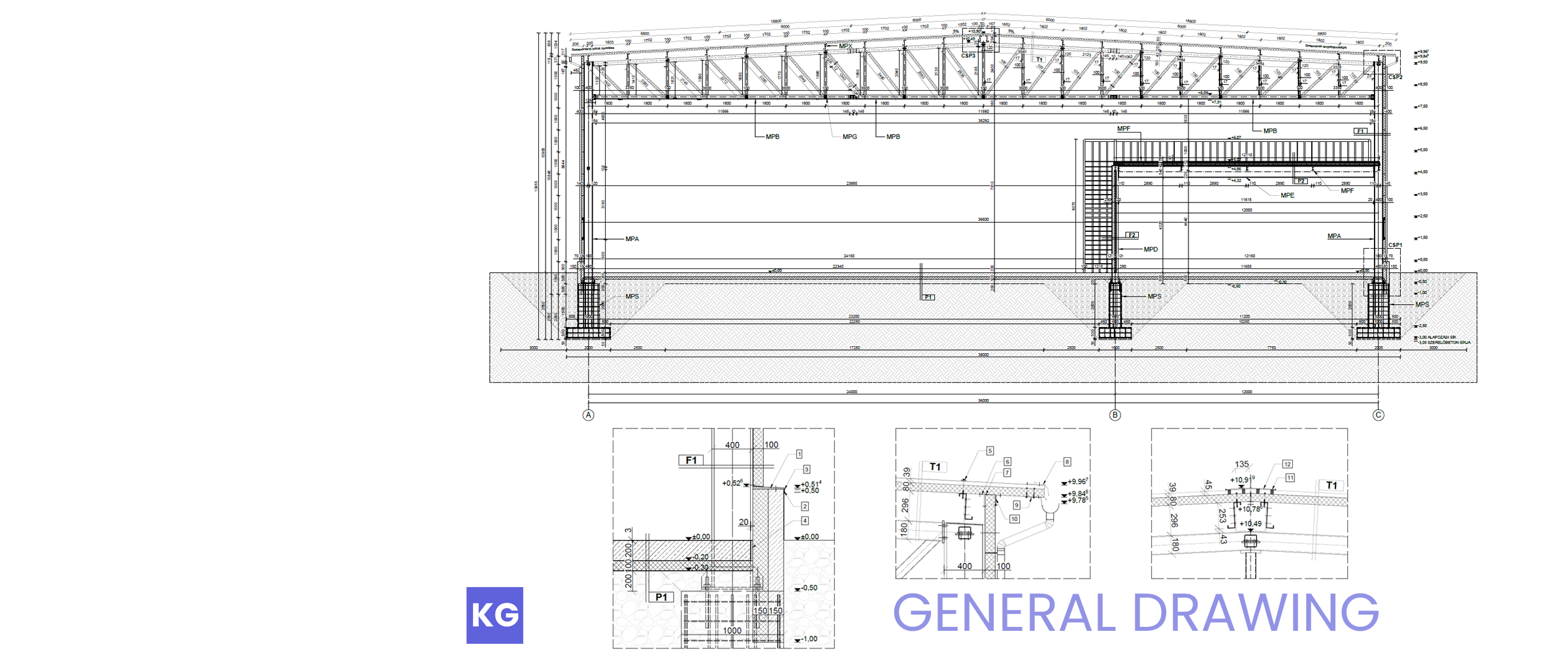
Generel arrangementstegning af den mellemliggende ramme med tre detaljer.
Oprettet i AutoCAD.

Konstruktionstegning for den typiske ramme.
Oprettet i Tekla Structures.

Forskallings-, dæk- og armeringstegning for kompositdækket.
Oprettet i Tekla Structures.

Facadetegning mod nordøst og sydøst.
Oprettet i ArchiCAD.

50 meter høj ståltårn med pultruderede FRP-tværarme, designet med henblik på vægtreduktion.
Denne hybride konstruktion var kernen i mit bachelorprojekt og modtog senere Diplomprisen fra den Ungarske Stålforening.
Konstruktionen bærer et dobbelt trefaset kredsløb med jordledere.
Lederne og jordlederne er monteret på henholdsvis de nederste seks og øverste to FRP-tværarme.
Stålkroppen består af:
Benstivere,
To typer hovedgitter,
To typer horisontalt afstivning,
Sekundær afstivning.
FE-model: 6DOF bjælkemodel med ledunderstøtninger.
Analyse: Elastisk, førsteordens
Standarder: EN 1993-3-1; EUR 27666 EN
Beregningerne bestod hovedsageligt af tværsnitsverifikationer i ULS, suppleret med i planen stabilitetskontroller af afstivningssystemerne. Begrænsning af trækspændinger i FRP-elementer viste sig nødvendig for at undgå krybesprække ved kvasi-varige belastninger.

Alle forbindelser blev beregnet manuelt.
Designet af disse samlinger blev udført i henhold til EN 1993-1-8 og EUR 27666 EN.
Brudformer for stålbolte inkluderer skær og tryk, samt nettotræk, stifttryk og udskæring for FRP-profiler.

Komplekse samlinger ved krydsningerne af tværarme.
Forbindelseskapaciteten i skrå samlinger viste sig at være den største udfordring ved brug af FRP, da dets ugunstige styrke måtte anvendes på grund af materialets ortotropi.

Snit af generel arrangementstegning for den nederste del af stålkonstruktionen.
Oprettet i Tekla Structures.

Snit af generel arrangementstegning for den øverste ledertværarm.
Oprettet i Tekla Structures.

36 meter spændvidde industrielt stålbygning med kompositdæk og trækstangsafstivning.
Dette omfattende projekt, udført som en del af mit industriprojektarbejde på BME, indeholder næsten 500 sider dokumentation og over 100 tekniske tegninger.
Rumlig og overfladedannelse var udgangspunktet for projektet.
Derfor skabte jeg den vertikale og horisontale opbygning af bygningen, tilpasset funktionerne. Jeg valgte også passende beklædningstyper til vægge, tag og gulv.
Dette blev udarbejdet i en skematisk BIM-model, detaljeret nok til at jeg kunne fortsætte designprocessen.

De mellemliggende rammers primære bærende elementer er svejsede stål-SHS gitterdragere samlet i tre dele.
Gavlene er portalrammer med koniske bjælker og bærende søjler for facadebeklædning.
Horisontale laster optages af trækstangsafstivning, som udviser materialenonlinearitet i modellen.
Et afskærmet område med kompositdæk er også implementeret for at understøtte forskellige funktioner i bygningen.

FE-model: 7DOF bjælkemodel med indspændte understøtninger.
Analyse: Ikke-lineær, andenordens.
Standarder: EN 1993-1-1, 1-3, 1-4, 1-5, 1-11; EN 1994-1-1; EN 1998-1.
Beregningerne omfatter dimensionering af sekundære elementer (sandwichelementer og Z-spær), kompositdæk, alle stål tværsnit, afstivning kun i træk og fundamenter.
Lokale og globale stabilitetskontroller samt seismiske responser blev også verificeret, sammen med nedbøjninger og sideforskydninger.

Samlinger, beslag, knudeforbindelser med gussetplader og svejsede forbindelser for primære gitterdragere blev alle verificeret ved manuelle beregninger i overensstemmelse med EN 1993-1-8.
Andre samlinger, såsom fodpladesamlinger for søjler og endeplader for gavlene, er blevet dimensioneret ved hjælp af Consteel Joint.

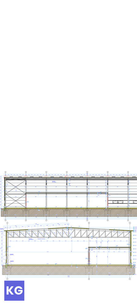
Plantegning af den færdige bygning med en konstruktionsvisning i øvre halvdel og en arkitektonisk visning i nedre.
Oprettet i AutoCAD.

Generel arrangementstegning af den mellemliggende ramme med tre detaljer.
Oprettet i AutoCAD.

Konstruktionstegning for den typiske ramme.
Oprettet i Tekla Structures.

Forskallings-, dæk- og armeringstegning for kompositdækket.
Oprettet i Tekla Structures.

Facadetegning mod nordøst og sydøst.
Oprettet i ArchiCAD.