Industrial Design
Complete projects fulfilling industrial requirements.
These solutions include adaptations, preliminary design variants, load calculations, structural and geotechnical design and answers to special requirements.
Complete projects fulfilling industrial requirements.
These solutions include adaptations, preliminary design variants, load calculations, structural and geotechnical design and answers to special requirements.

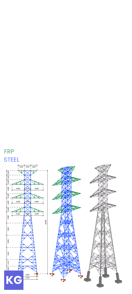
50-meter-high steel support tower with pultruded FRP crossarms intended for weight reduction.
This hybrid structure was the core of my BSc thesis, and later won the Diploma Award of the Hungarian Steel Association.

The structure supports a dual three-phase circuit with earthing wires.
The conductors and earthing wires are mounted to the lower six and upper two FRP crossarms, respectively.
The steel body consists of:
Leg members,
Two types of main lattices,
Two types of horizontal bracing,
Secondary bracing.

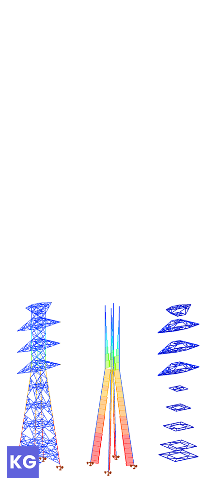
FE model: 6DOF beam model with hinged supports.
Analysis: Elastic, first-order.
Standards: EN 1993-3-1; EUR 27666 EN
Calculations mainly consisted of cross-sectional verifications in ultimate limit state, supplemented by in-plane buckling verifications of bracing systems. Limiting tensile stresses for FRP members proved to be necessary to avoid creep fissures under quasi-permanent loads.

All connections were calculated manually.
Design of these joints was carried out based on EN 1993-1-8 and EUR 27666 EN.
Failure modes for steel bolts include shear and bearing, and net tension, pin-bearing, and shear-out for FRP profiles.

Complex joints at the intersections of crossarms.
Connection resistances in slanted joints proved to be the main setback of using FRP, since its unfavorable strength had to be used due to orthotropy.

General arrangement drawing for the lowest part of the steel body.
Created with Tekla Structures.

General arrangement drawing for the upper conductor crossarm.
Created with Tekla Structures.

50-meter-high steel support tower with pultruded FRP crossarms intended for weight reduction.
This hybrid structure was the core of my BSc thesis, and later won the Diploma Award of the Hungarian Steel Association.
The structure supports a dual three-phase circuit with earthing wires.
The conductors and earthing wires are mounted to the lower six and upper two FRP crossarms, respectively.
The steel body consists of leg members, two types of main lattices, two types of horizontal bracing and secondary bracing.
FE model: 6DOF beam model with hinged supports.
Analysis: Elastic, first-order.
Standards: EN 1993-3-1; EUR 27666 EN
Calculations mainly consisted of cross-sectional verifications in ultimate limit state, supplemented by in-plane buckling verifications of bracing systems. Limiting tensile stresses for FRP members proved to be necessary to avoid creep fissures under quasi-permanent loads.

All connections were calculated manually.
Design of these joints was carried out based on EN 1993-1-8 and EUR 27666 EN.
Failure modes for steel bolts include shear and bearing, and net tension, pin-bearing, and shear-out for FRP profiles.

Complex joints at the intersections of crossarms.
Connection resistances in slanted joints proved to be the main setback of using FRP, since its unfavorable strength had to be used due to orthotropy.

General arrangement drawing sections for the lowest part of the steel body.
Created with Tekla Structures.

General arrangement drawing sections for the upper conductor crossarm.
Created with Tekla Structures.

36-meter span industrial steel building with a steel deck and tie-rod bracing.
This extensive project, completed as part of my industrial projectwork at BME, contains nearly 500 pages of documentation and over 100 technical drawings.

Spatial and surface formation were the starting point of the project.
Therefore, I created the vertical and horizontal arrangement of the building, corresponding with functionalities. I also chose appropriate cladding types for the walls, roof and floor.
This was prepared in a schematic BIM-model, detailed enough for me to continue designing with.

The intermediate frames’ primary structural members are welded steel SHS trusses assembled in three parts.
Gable ends are portal frames, with tapered girders and supporting columns for facade cladding.
Horizontal loads are carried by tie-rod bracing, which present a material nonlinearity in the model.
A secluded space with a steel deck floor has also been implemented to support different functions inside the building.

FE model: 7DOF beam model with fixed supports.
Analysis: Nonlinear, second-order.
Standards: EN 1993-1-1, 1-3, 1-4, 1-5, 1-11; EN 1994-1-1; EN 1998-1.
Calculations include design of the secondary members (sandwich panels and Z-purlins), composite slab, all steel cross-sections, tension-only bracing and foundations.
Local and global stability checks and seismic responses were also verified, along with deflections and drifts.

Splices, fittings, gusset plate connections, and welded connections for the main lattice girders were all verified by manual calculation, in accordance with EN 1993-1-8.
Other joints, such as base plate connections for columns, end plates for the gable ends have been designed via Consteel Joint.

Floor plan of the finished building, with a structural view on the left half, and an architectural view on the right.
Created with AutoCAD.
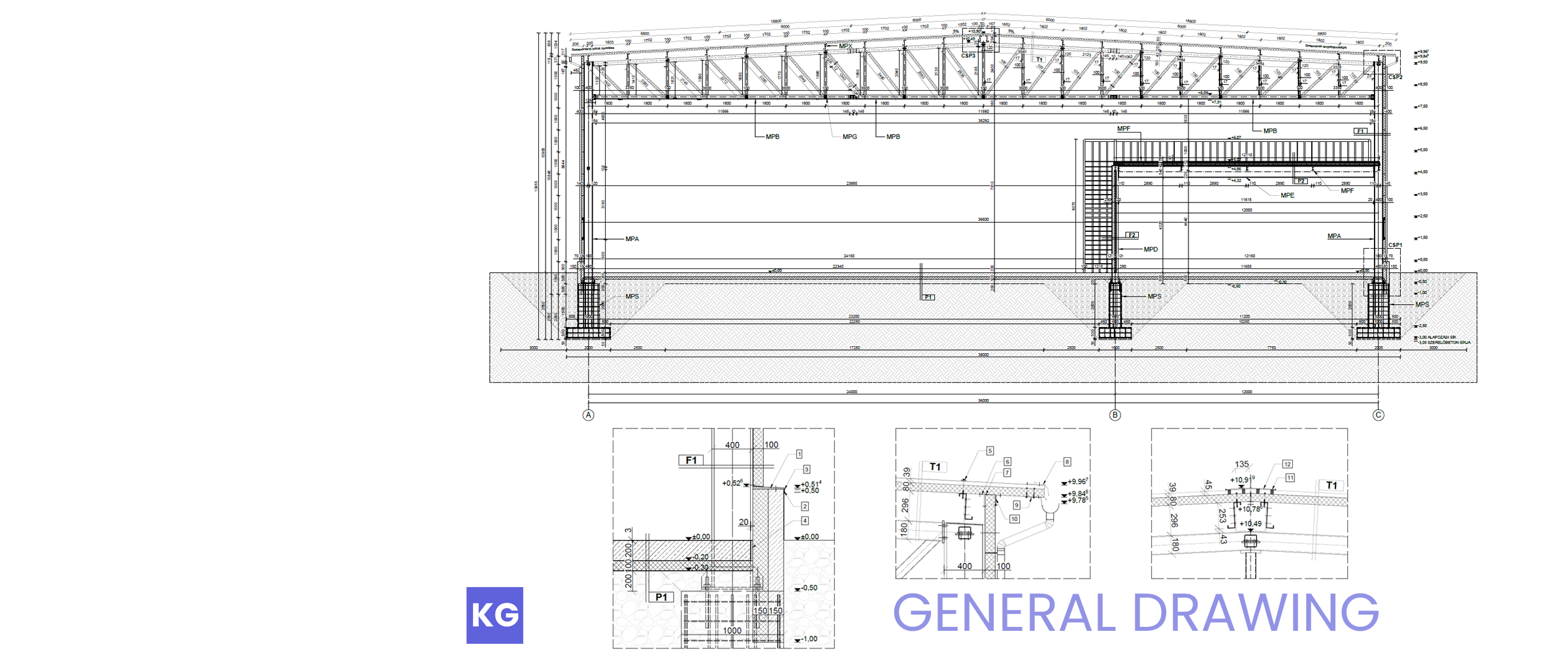
General arrangement drawing of the intermediate frame, with three details.
Created with AutoCAD.

Structural drawing of the typical frame.
Created with Tekla Structures.

Formwork, floor slab, and reinforcement drawings for the steel deck.
Created with Tekla Structures.

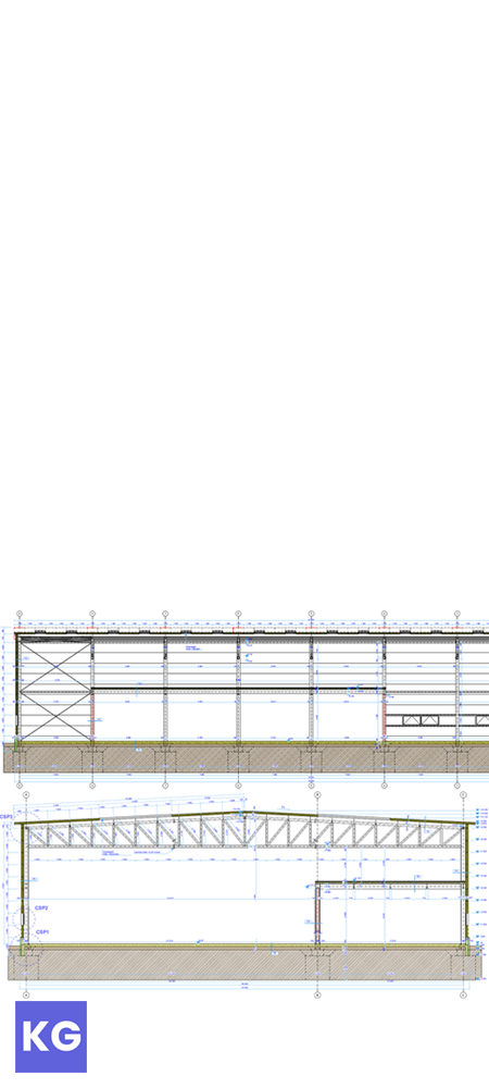
Facade plans from the northeastern and southeastern views.
Created with ArchiCAD.

36-meter span industrial steel building with a steel deck and tie-rod bracing.
This extensive project, completed as part of my industrial projectwork at BME, contains nearly 500 pages of documentation and over 100 technical drawings.
Spatial and surface formation were the starting point of the project.
Therefore, I created the vertical and horizontal arrangement of the building, corresponding with functionalities. I also chose appropriate cladding types for the walls, roof and floor.
This was prepared in a schematic BIM-model, detailed enough for me to continue designing with.

The intermediate frames’ primary structural members are welded steel SHS trusses assembled in three parts.
Gable ends are portal frames, with tapered girders and supporting columns for facade cladding.
Horizontal loads are carried by tie-rod bracing, which present a material nonlinearity in the model.
A secluded space with a steel deck floor has also been implemented to support different functions inside the building.

FE model: 7DOF beam model with fixed supports.
Analysis: Nonlinear, second-order.
Standards: EN 1993-1-1, 1-3, 1-4, 1-5, 1-11; EN 1994-1-1; EN 1998-1.
Calculations include design of the secondary members (sandwich panels and Z-purlins), composite slab, all steel cross-sections, tension-only bracing and foundations.
Local and global stability checks and seismic responses were also verified, along with deflections and drifts.

Splices, fittings, gusset plate connections, and welded connections for the main lattice girders were all verified by manual calculation, in accordance with EN 1993-1-8.
Other joints, such as base plate connections for columns, end plates for the gable ends have been designed via Consteel Joint.

Floor plan of the finished building, with a structural view on the upper half, and an architectural view on the lower half.
Created with AutoCAD.

General arrangement drawing of the intermediate frame, with three details.
Created with AutoCAD.

Structural drawing of the typical frame.
Created with Tekla Structures.

Formwork, floor slab, and reinforcement drawings for the steel deck.
Created with Tekla Structures.

Facade plans from the northeastern and southeastern views.
Created with ArchiCAD.